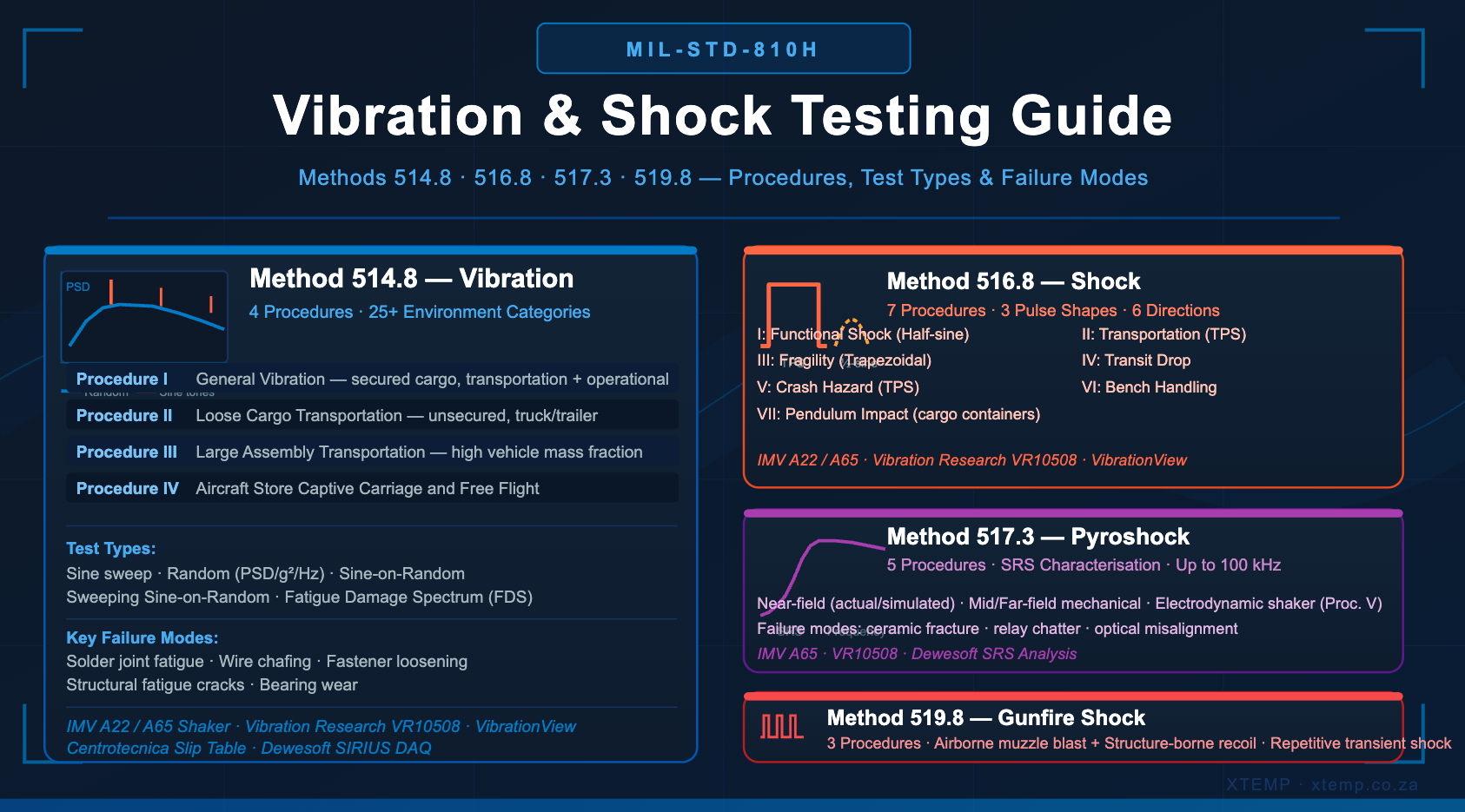
Vibration and shock are the most mechanically destructive environmental stresses that military and aerospace equipment encounters across its life cycle. From the sustained random vibration of a wheeled vehicle traversing rough terrain, to the transient impulse of a crash event, to the extreme high-frequency energy of a pyrotechnic separation — each stress type demands a different test method, a different test setup, and a different analysis approach. This guide covers MIL-STD-810H Methods 514.8, 516.8, 517.3, and 519.8 in technical detail.
The Role of Vibration and Shock in MIL-STD-810H
MIL-STD-810H — the United States Department of Defense environmental engineering standard, current version released in 2019 — dedicates a substantial portion of its test method library to mechanical dynamics. Where climatic methods (temperature, humidity, altitude, solar) test the effects of environmental exposure over time, mechanical dynamic methods test the effects of energy transferred into a structure through motion — energy that can crack solder joints, fatigue metal, loosen fasteners, shatter electronic components, and degrade seals.
Every piece of military equipment spends its life cycle experiencing mechanical dynamic stress. It is transported in the back of a truck across unpaved roads, flown in a helicopter or fixed-wing aircraft, mounted on a vehicle that fires weapons, and potentially subjected to crash events or explosive device detonations nearby. Each of these environments has a distinct mechanical signature — a characteristic combination of frequency content, amplitude, duration, and waveform shape — that MIL-STD-810H translates into specific laboratory test procedures.
The standard’s critical philosophy of tailoring applies equally to vibration and shock testing. The test engineer’s first responsibility is to understand the product’s actual life cycle environment — what platforms it will be installed on, what events it will experience, at what mounting locations — and select the appropriate method, procedure, and vibration category accordingly. Using an incorrect or generic test profile wastes test time and provides no meaningful qualification evidence.
This guide covers four mechanical dynamic test methods and their application to South African defence, aerospace, automotive, and electronics qualification programmes.
Method 514.8 — Vibration
Purpose: To determine the ability of a product to withstand the vibration environments it will encounter during transportation and operation throughout its service life — and to identify the design margin available before vibration-induced failure occurs.
Vibration testing is one of the most comprehensive and technically complex methods in MIL-STD-810H. Method 514.8 encompasses more than 25 defined vibration environment categories covering every major platform type, and requires careful engineering judgement in selecting which categories apply to a given product’s life cycle profile.

The Four Procedures
Procedure I — General Vibration is the primary procedure for most equipment and covers the broadest range of application. It applies to any system that will be secured or tied down during transportation, or that will be deployed on a vehicle platform at any point in its operational life. The procedure addresses both transportation conditions (vibration during shipment from factory to deployment) and operational conditions (vibration during use on the intended platform).
The test item is secured to the vibration table through a fixture that replicates its actual mounting interface — the connector between the product and the platform. This mounting interface is critical: the vibration response of the product depends heavily on the fixture stiffness, mass distribution, and boundary conditions. A poorly designed fixture that introduces resonances not present in the real installation will produce misleading results.
Testing is performed in all three orthogonal axes (X, Y, Z) with sufficient exposure in each axis to account for the vibration the product will accumulate across its full service life. The standard uses Fatigue Damage Spectrum (FDS) analysis to ensure the test profile accumulates the same fatigue damage potential as the real-world environment — preventing both under-testing (missing real failures) and over-testing (introducing failures that would never occur in service).
Procedure II — Loose Cargo Transportation applies to equipment that will be transported in trucks or trailers as unsecured cargo — not tied down, not in a fixed mounting. The test item is placed on the vibration table without being bolted down, and fencing or barriers are installed around it to prevent it falling off the table during the test. This procedure specifically targets packaging adequacy, the ability of equipment to survive rough handling without fixturing, and the risk of internal components shaking loose during shipment.
Procedure III — Large Assembly Transportation applies to large collections of equipment or assemblies that form a significant proportion of the vehicle’s total mass when being transported on wheeled or tracked vehicles. When a test item represents a large fraction of the vehicle mass, the standard vibration input profiles for standard cargo no longer apply — the mass of the test item itself modifies the vehicle’s vibration behaviour. This procedure accounts for that interaction.
Procedure IV — Assembled Aircraft Store Captive Carriage and Free Flight applies specifically to stores (weapons, sensor pods, external fuel tanks, or other equipment) that are fixed to the external hardpoints of aircraft. These items experience a combination of aerodynamic buffeting, acoustic excitation, and aircraft structural vibration that is distinct from the vibration experienced by equipment inside the airframe. The procedure uses vibration exciters driving the test item directly or through a fixture representative of the store-to-aircraft interface.
Vibration Types — Sine, Random, and Mixed Mode
A critical aspect of Method 514.8 is the selection of the correct type of vibration input for each environment category. The standard defines several vibration signal types, each replicating a different class of real-world excitation:
Sinusoidal Vibration expresses vibration as a single frequency (or a sweep across a frequency range) at a defined acceleration amplitude. Sine vibration is characterised by a fundamental frequency and its harmonics. In practice, purely sinusoidal environments arise from rotating machinery — engines, propellers, and turbines — where the excitation is dominated by the shaft rotation frequency and its integer multiples. Sine sweep testing identifies resonant frequencies in the test item: as the excitation frequency is swept across the specified range (typically 5 Hz to 2,000 Hz at a defined sweep rate), the test item responds with amplified motion at its structural resonances. These resonant frequencies are critical data — they reveal the frequencies at which the product is most vulnerable to damage.
Random Vibration is a broadband, statistically described vibration environment that has no periodic structure. It is characterised by a Power Spectral Density (PSD) — a curve expressing vibration energy (in g²/Hz) as a function of frequency. Random vibration represents environments dominated by turbulence, aerodynamic buffeting, road surface irregularities, and acoustic excitation — all of which produce energy distributed broadly across the frequency spectrum rather than at discrete frequencies. It is the most commonly used vibration type for ground vehicle and jet aircraft equipment qualification.
The overall vibration severity is expressed as the Root Mean Square (RMS) acceleration in g — the square root of the area under the PSD curve. A typical ground vehicle random vibration profile might specify levels of 0.04 g²/Hz across a frequency range of 10 to 1,000 Hz, producing an overall RMS level of around 5 to 8 g depending on the exact spectral shape.
Sine-on-Random combines a broadband random background with one or more discrete sinusoidal tones superimposed on it simultaneously. This mixed-mode vibration type is the defining characteristic of helicopter environments, where the broadband random vibration of aerodynamic turbulence coexists with the strong periodic vibration at the main rotor blade passage frequency and its harmonics. For a typical military helicopter under Category 14 of Method 514.8, the broadband random levels are specified across a frequency range up to 500 Hz, with discrete sine tones corresponding to the 1P (main rotor) frequency and its blade passage harmonics superimposed.
Sweeping Sine-on-Random extends the sine-on-random concept by sweeping the sinusoidal tones across a frequency range during the test, allowing the test to probe a broader range of potential resonant responses while maintaining the mixed-mode character of the environment.
The standard explicitly cautions against combining spectral shapes inappropriately — for example, superimposing a sine-on-random helicopter spectrum on top of a broadband wheeled vehicle random spectrum creates a non-physical profile that does not represent any real environment. Test specification must be grounded in the actual platform environments the product will experience.
Vibration Environment Categories
Method 514.8 organises the vibration environments its procedures must replicate into more than 25 defined categories, each representing a specific platform type and operational scenario. The most commonly encountered include:
Category 4 — Common Carrier (Ground Transport): The vibration environment experienced by cargo in commercial highway trucks and military logistics vehicles during road transport. This is the baseline transportation vibration category and applies to virtually every piece of equipment that moves by road.
Category 7 — Jet Aircraft: Vibration experienced by equipment mounted inside fixed-wing jet aircraft. The environment is predominantly broadband random, driven by aerodynamic boundary layer turbulence on the airframe surface and acoustic excitation from the engines. Levels and frequency ranges vary significantly with mounting location (fuselage, wing, engine nacelle).
Category 8 — Propeller Aircraft: Equipment on propeller-driven aircraft experiences a sine-on-random environment, with the random background from aerodynamic sources and discrete sine tones at the propeller blade passage frequency.
Category 9 — Helicopter (Rotary Wing): Helicopter vibration is the most complex of the standard environments. The sine-on-random profile reflects the strong periodic excitation from main and tail rotor blade passage frequencies superimposed on broadband turbulence. Because helicopter vibration is characterised by dominant peaks at rotor harmonics, equipment mounted on helicopters requires sine-on-random vibration control capability that can maintain both the broadband random levels and the swept or fixed sine tones simultaneously and independently.
Categories 10–13 — Ground Vehicles (Wheeled and Tracked): The vibration environments for wheeled military vehicles (HMMWVs, trucks, APCs) and tracked vehicles (tanks, self-propelled artillery) differ significantly. Tracked vehicles introduce strong periodic vibration at the track frequency (sprocket tooth passage) in addition to broadband random from terrain irregularities. Equipment mounted directly on the hull or turret of a tracked vehicle experiences some of the most severe vibration in the standard.
Category 15 — Ships and Surface Vessels: Naval equipment experiences sinusoidal vibration from propeller shaft rotation and blade passage, with the vibration characteristics strongly dependent on the vessel’s speed and propulsion system. The frequency range is typically low (below 100 Hz) but sustained for very long periods.
What Vibration Testing Reveals
Method 514.8 specifically targets the following failure modes:
Solder joint fatigue is the most common vibration-induced failure in electronic equipment. Printed circuit boards flex in response to vibration, and the solder joints connecting surface-mount components to the board accumulate fatigue damage with each vibration cycle. The rate of damage accumulation depends on the component mass, the PCB natural frequency, and the vibration level. A circuit board that resonates within the input frequency range amplifies the applied vibration — potentially by a factor of 5 to 20 — dramatically accelerating fatigue at the most heavily loaded solder joints.
Wire and cable chafing occurs when vibration causes wires and harnesses to rub repeatedly against enclosure walls, mounting brackets, or each other. The abrasion progressively removes insulation, eventually causing shorts or opens that may be intermittent and difficult to reproduce in a static inspection.
Fastener loosening results from the cyclic vibration loads imposed on threaded fasteners. Without adequate locking features (thread-locking compound, lock washers, or prevailing torque nuts), fasteners can progressively rotate and back out under vibration, causing structural looseness that changes the system’s dynamic response and can lead to complete detachment.
Bearing and gear wear in mechanical systems is accelerated by off-design vibration loads, particularly at frequencies near the bearing’s natural frequency.
Structural fatigue cracks initiate at stress concentrations — notches, holes, weld toes, and sharp corners — under cyclic vibration loading, and propagate progressively until fracture.
Method 516.8 — Shock
Purpose: To evaluate the effects of mechanical shock on a product — the transient transmission of kinetic energy that occurs during sudden velocity changes — including the structural integrity and functional performance of the product during and after shock events.
Shock events are fundamentally different from vibration. While vibration is a sustained, ongoing excitation measured in seconds to hours, a shock is a transient event typically lasting milliseconds — but delivering energy at very high acceleration levels, often hundreds or thousands of g. The short duration means that the product’s inertia prevents it from responding quasi-statically: different parts of the structure respond at different rates, causing internal differential displacements that place bonds, solder joints, connectors, and structural interfaces under sudden, severe stress.
Method 516.8 provides seven procedures covering the full spectrum of shock events a military product may encounter:
Procedure I — Functional Shock assesses whether a product continues to operate correctly during and immediately after a shock event. This procedure uses classical shock pulses — most commonly the half-sine pulse for high-speed craft applications — and is performed while the product is in its operational configuration and powered. The test identifies shock-induced functional failures such as relay chatter, memory corruption, connector dropout, and loss of mechanical alignment.
Procedure II — Transportation Shock replicates the shock events experienced during logistic transportation — truck bed impacts at road joints and potholes, railway humping operations, and cargo handling. The standard specifies terminal peak sawtooth (TPS) pulses as the default classical pulse shape for this procedure, reflecting the character of real transportation impacts. The test item is tested in its shipping or storage configuration, not necessarily in its operational configuration.
Procedure III — Fragility is unique among the shock procedures in that its purpose is not to demonstrate compliance with a specified level, but rather to determine the product’s fragility level — the threshold shock input at which structural or functional degradation first occurs. This test is performed early in the development programme, before the product design is finalised, using trapezoidal shock pulses that progressively increase in severity until degradation is observed. The fragility level determined from this procedure informs the design of packaging, shock mounts, and stowage configurations needed to protect the product in service.
Procedure IV — Transit Drop is a physical drop test simulating the shocks that occur when equipment is dropped during handling — from a workbench, from the back of a vehicle, or during loading and unloading operations. The test item, either in its shipping case or as prepared for field use, is dropped from specified heights onto a hard surface. This procedure is distinct from Procedure II in that it targets handling drops rather than transportation vibration and shock.
Procedure V — Crash Hazard Shock is specifically designed for equipment mounted in air or ground vehicles. It evaluates whether the equipment will detach from its mounts and become a projectile during a crash event — a secondary hazard that could injure occupants or damage the vehicle. The test uses terminal peak sawtooth pulses applied in both directions of all three orthogonal axes. Failure criterion for this procedure is breakaway from the mounting — the product is not required to function after the crash event, but it must not become a dangerous unrestrained mass.
Procedure VI — Bench Handling evaluates the shock resistance of equipment during typical bench handling, maintenance, and packaging operations — the minor impacts and drops that occur during repair and servicing. This procedure is highly specific to the product type and maintenance procedures, and must be tailored on a case-by-case basis. It is particularly relevant for equipment with external protrusions — antennas, connectors, handles — that may be damaged by bench impacts without gross structural failure of the main assembly.
Procedure VII — Pendulum Impact addresses the shock events experienced by equipment inside bulk cargo shipping containers (ISO containers, CONEX boxes) during rough handling. The pendulum impact test uses a swinging mass to deliver controlled impulse loads to the container — simulating the impacts that occur during stacking, crane lifting, and rough vehicle transport.
Shock Pulse Shapes
The shape of the shock pulse determines its frequency content and therefore which failure modes it will excite. Method 516.8 specifies three classical pulse shapes:
Terminal Peak Sawtooth (TPS) is the default pulse shape for most shock procedures. It ramps up linearly from zero to its peak acceleration value, then drops instantly to zero — producing a broad, relatively flat Shock Response Spectrum (SRS) that excites a wide range of structural frequencies. The TPS is preferred because its SRS shape is a reasonable approximation of many real shock environments encountered in transportation and crash events.
Half-Sine Pulse is a smooth, symmetric pulse — rising sinusoidally from zero to peak and back to zero. It produces a more concentrated SRS than the TPS, with less energy at high frequencies. The half-sine is specified for Procedure I (Functional Shock) in high-speed craft applications and for cases where the measured field environment is better represented by this pulse shape.
Trapezoidal Pulse rises abruptly to its peak value, holds at that level for a defined duration, then drops abruptly. This pulse shape produces high energy at low frequencies, making it appropriate for Procedure III (Fragility) where the goal is to systematically increase static-equivalent shock levels to find the fragility threshold.
All three axes must be tested in both positive and negative directions — meaning a minimum of six shock applications per procedure at each specified level.
Method 517.3 — Pyroshock
Purpose: To evaluate the ability of a product to withstand the extreme, high-frequency shock environment produced by the detonation or ignition of a pyrotechnic device — such as explosive separation bolts, rocket motor ignition, jettison systems, or missile stage separation.
Pyroshock is qualitatively different from the classical shock events addressed in Method 516.8. Where a transportation drop produces a smooth half-sine or sawtooth pulse lasting 5 to 20 milliseconds, a pyroshock event is characterised by extremely high accelerations (hundreds to thousands of g), very short durations (sub-millisecond), and energy concentrated at high frequencies (typically 100 Hz to 100 kHz). This high-frequency energy propagates through the structure as stress waves rather than rigid body motion, exciting structural resonances that are far above the frequency range addressed by conventional shock testing.
The failure modes uniquely associated with pyroshock include: fracture of ceramic capacitors, crystal oscillators, and other brittle electronic components; relay chatter and contact bounce at high frequency; failure of glass-to-metal seals; potentiometer track damage; and optical misalignment in precision electro-optical systems.
Method 517.3 provides five procedures spanning the full range of pyroshock test approaches from closest to the pyrotechnic source (near-field) to furthest (far-field):
Procedure I — Near-Field with Actual Configuration uses the actual intended pyrotechnic device, detonated in the actual platform configuration. This is the most realistic but also the most expensive and operationally complex procedure. It requires access to the actual vehicle or platform structure, the actual pyrotechnic device, and appropriate explosive test facilities.
Procedure II — Near-Field with Simulated Configuration reduces cost by mounting the test item on a steel plate in a simplified configuration that approximates the transmission path of the real installation. The actual pyrotechnic device is still used, but the full platform assembly is not required.
Procedure III — Mid-Field with Mechanical Test Device replaces the explosive device with mechanical shock machines — the same equipment used for MIL-DTL-901 shipboard shock testing or resonant beam shock machines. The mechanical impulse is calibrated to produce an SRS equivalent to the mid-field pyroshock environment. Shocks are applied to all three orthogonal axes.
Procedure IV — Far-Field with Mechanical Device follows the same approach as Procedure III but at reduced severity levels appropriate for equipment located further from the pyrotechnic source in the actual platform.
Procedure V — Far-Field with Electrodynamic Shaker is the most laboratory-accessible pyroshock procedure — it uses the same electrodynamic vibration shakers employed for Method 514.8 vibration testing, driven with a synthesised waveform designed to replicate the far-field pyroshock SRS. The waveform is typically synthesised from a superposition of damped sinusoids. Importantly, the standard specifies that classical shock pulse shapes (half-sine, TPS) must not be used for Procedure V — only SRS-matched waveform replication is appropriate.
The Shock Response Spectrum (SRS) is the universal characterisation tool for pyroshock environments. It expresses the peak acceleration response of a damped single-degree-of-freedom oscillator at each frequency across the spectrum, for a given base input — providing a frequency-domain picture of the shock’s potential to excite structural resonances at each frequency. SRS analysis requires specialised data acquisition and analysis software; XTEMP’s Dewesoft SIRIUS data acquisition systems with DewesoftX software provide full SRS computation and display capability.
Method 519.8 — Gunfire Shock
Purpose: To evaluate the structural integrity and functional performance of equipment likely to be exposed to the shock and vibration environment generated by the firing of guns mounted on or near the platform carrying the equipment.
Gunfire creates a highly specific mechanical environment: a repetitive transient shock at the firing rate of the weapon, combined with broadband random vibration from muzzle blast pressure and structure-borne transmission through the gun mechanism. The repetitive nature of gunfire — potentially hundreds of rounds per minute — means that even low-amplitude individual shocks can accumulate significant fatigue damage through the firing burst, particularly at structural resonances that respond cumulatively to each successive impulse.
The method distinguishes two primary sources of gunfire-induced stress: airborne muzzle blast pressure, which impinges on exposed surfaces of equipment mounted near the gun muzzle; and structure-borne shock transmitted through the gun mounting and airframe or vehicle structure.
Three procedures address different gunfire scenarios:
Procedure I covers equipment where both airborne muzzle blast pressure and structure-borne shock are present — the most complete gunfire environment. This applies to equipment in close proximity to the gun on an aircraft or vehicle.
Procedure II addresses the structure-borne shock path alone — relevant for equipment mounted on the same platform but shielded from direct muzzle blast exposure.
Procedure III covers the airborne acoustic and pressure path alone — relevant for equipment exposed to muzzle blast but not in the structural transmission path of the gun recoil.
The test replicates a gunfire schedule that specifies the number of rounds, the firing rate, and the burst duration — parameters derived from the weapon system’s expected operational firing schedule. Failure modes targeted by Method 519.8 include structural fatigue from cumulative low-cycle shock loading, relay chatter and contact bounce at the firing frequency, solder joint fatigue from repeated impulse loading, and deformation of light structural members under repeated blast pressure loading.
Method 520.5 — Combined Temperature, Humidity, Vibration, and Altitude
Vibration and shock do not occur in isolation. Equipment mounted on a helicopter at high altitude operates simultaneously in a low-pressure, low-temperature environment with sustained sine-on-random vibration. Electronic equipment in a desert vehicle experiences high temperature and sustained random vibration together. Method 520.5 addresses these synergistic combined environments — recognising that the combined stress of multiple simultaneous environmental inputs can produce failure modes that would not appear if each input were applied separately.
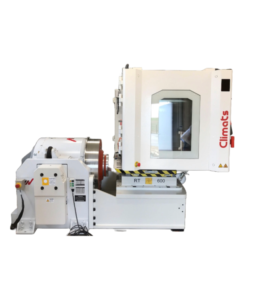
For vibration qualification programmes where the product’s deployment environment combines thermal and mechanical stress, the tailored test programme should include consideration of Method 520.5 combined testing in addition to the individual method qualifications described above.
Test Axes, Fixturing, and Control Strategy
Three critical engineering decisions apply to every vibration and shock test:
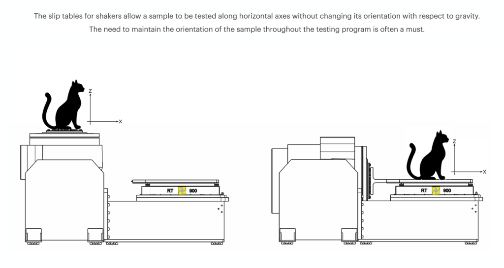
Test axes: All mechanical dynamic methods in MIL-STD-810H require testing in three orthogonal axes — typically the product’s vertical (Z), lateral (Y), and longitudinal (X) axes as defined by its mounting orientation. Each axis must receive the full specified exposure. For shock testing, both directions of each axis (positive and negative) must be covered, giving a minimum of six shock test directions.
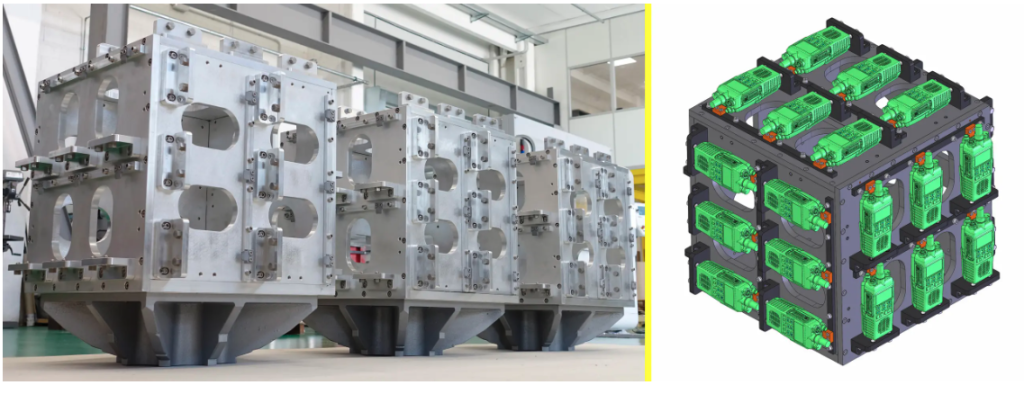
Fixturing: The mechanical interface between the test item and the shaker table is critical. A fixture that is too stiff relative to the test item will not allow the item to respond dynamically. A fixture with resonances within the test frequency range will amplify inputs at those frequencies and attenuate them elsewhere — distorting the test environment. Fixture design for high-frequency or high-force vibration testing is a specialist discipline, and the fixture must be verified before the test to confirm it does not introduce significant resonances within the test band.
Control strategy: Method 514.8 supports input control (the traditional approach — accelerometers at the fixture/test item interface, closed-loop control to the specified PSD), response control (controlling to a specified vibration level at a point on the test item itself), and force limiting (limiting the force at the fixture interface to prevent over-testing of items whose mass modifies the table dynamics). The appropriate control strategy depends on the test item’s mass, the fixture design, and the guidance in Annex A of the method.
XTEMP — Vibration and Shock Test Systems for MIL-STD-810H in South Africa
XTEMP is Southern Africa’s specialist in environmental test systems, and our vibration product range covers the full spectrum of MIL-STD-810H mechanical dynamic test requirements.
IMV Corporation Electrodynamic Shakers
XTEMP is the South African representative for IMV Corporation — a Japanese manufacturer of electrodynamic shaker systems renowned for high-precision vibration control and energy-efficient ECO-drive technology.
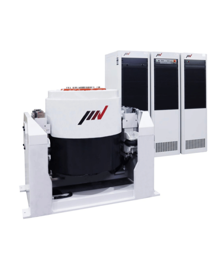
The IMV A-Series air-cooled ECO electrodynamic shaker delivers up to 74 kN of sine and random force with a shock capability of 220 kN, across a frequency range of 0 to 3,300 Hz. With a maximum payload of 300 kg and displacement of 76 mm peak-to-peak, the A-Series covers the complete Method 514.8 frequency range for most ground vehicle, rotary wing, and fixed wing equipment categories, as well as Methods 516.8 (shock) and 519.8 (gunfire shock).
The IMV K-Series delivers up to 350 kN sine force for larger assemblies and higher-force test requirements — appropriate for large sub-system level testing under Method 514.8 Procedure III and for severe military shock environments under Method 516.8.
IMV’s ECO system continuously monitors the force required for the current test profile and automatically adjusts field power and cooling blower speed to operate at minimum energy consumption — reducing operating costs and system noise for the majority of test profiles without any performance compromise at rated force.
Vibration and Temperature combined Tests
XTEMP vibration portfolio to cover a broader range of force levels and test configurations, including combined climatic-vibration systems for Method 520.5 testing.
Vibration Research Controllers — VR10508 and VibrationView Software
Control system quality is as important as shaker quality for MIL-STD-810H compliance. XTEMP supplies Vibration Research VR10500 controllers running VibrationView software — providing full control capability for:
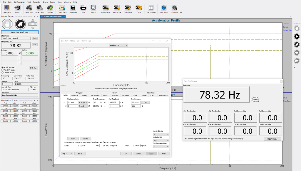
- Random vibration to specified PSD profiles (Method 514.8)
- Sine sweep and sine dwell (Method 514.8 resonance search)
- Sine-on-random for helicopter environments (Category 14, Method 514.8)
- Classical shock pulses — TPS, half-sine, and trapezoidal (Method 516.8)
- SRS-matched waveform replication for pyroshock (Method 517.3 Procedure V)
- Gunfire shock sequences (Method 519.8)
VibrationView generates test profiles from pre-defined standard templates including MIL-STD-810H categories, creates and stores programme sequences for repeat testing, and produces full data reports including PSD plots, SRS analysis, resonance tracking, and pass/fail documentation. The 8-channel capability allows simultaneous multi-point measurement and response monitoring across the test item.
Dewesoft SIRIUS Data Acquisition
Comprehensive vibration and shock testing requires more than control — it requires measurement and analysis of the test item’s response throughout the test. XTEMP’s Dewesoft SIRIUS data acquisition systems, running DewesoftX software, provide:
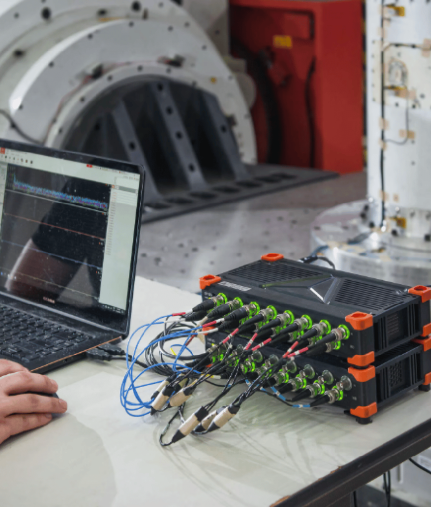
- High-speed, multi-channel acceleration measurement simultaneously with vibration control
- Real-time SRS computation for pyroshock and shock response analysis (Method 517.3)
- Simultaneous multi-physics measurement — combining vibration response with temperature, strain, and electrical signal data in a single acquisition session
- Full test documentation output meeting MIL-STD-810H data traceability requirements
The Dewesoft 7-year warranty and all-in-one software architecture make it the most cost-effective and capable DAQ solution for comprehensive MIL-STD-810H vibration and shock test programmes.
Centrotecnica Slip Tables
For horizontal axis vibration testing — required in all three-axis test programmes — XTEMP supplies Centrotecnica rail-guided slip tables, providing precise, low-friction horizontal translation of the shaker’s vertical excitation force. The rail-guided design eliminates the frequency-dependent stiffness variations of oil-film hydrostatic tables, delivering accurate low-frequency response that is critical for the long-stroke, low-frequency profiles in Method 514.8 ground vehicle categories.
Equipment Summary for MIL-STD-810H Vibration and Shock Testing
| MIL-STD-810H Method | XTEMP Equipment |
|---|---|
| 514.8 Vibration — Random, Sine, Sine-on-Random | IMV shaker + Vibration Research |
| 514.8 Horizontal axis testing | Centrotecnica Rail-Guided Slip Table |
| 516.8 Shock — Classical pulses (TPS, half-sine, trapezoidal) | IMV shaker + Vibration Research |
| 517.3 Pyroshock (Procedure V — Electrodynamic shaker) | IMV Shaker + Vibration Research + Dewesoft SRS analysis |
| 519.8 Gunfire Shock | IMV Shaker + Vibration Research + Dewesoft DAQ |
| 520.5 Combined Vibration + Temperature | Combined Climatic-Vibration Systems |
| Measurement and data acquisition — all methods | Dewesoft SIRIUS + DewesoftX software |
All systems are supplied with full installation, commissioning, operator training, test programme configuration, and ongoing calibration support. XTEMP’s technical team assists with test plan development, method tailoring, profile specification, and fixture design guidance.
We serve defence contractors, aerospace manufacturers, satellite and space companies, electronics OEMs, and automotive suppliers across Southern Africa — from our offices in Pretoria and Cape Town.
Contact XTEMP to discuss your MIL-STD-810H vibration and shock testing requirements:
📞 Pretoria: +27 12 443 6565 📞 Cape Town: +27 21 974 6227 📧 info@xtemp.co.za 🌐 www.xtemp.co.za